How to read (And Understand) a Hex File - PIC Microcontrollers
Programming From the Eyes of a Machine
Shoutout to Microchip Technology

In this article you'll find:

Introduction
As I was creating a PIC ICSP Programmer with Arduino, I'd learn a lot about microcontrollers, from Their different approaches to programming:
- The C Based High-Level Programming.
- The Assembler, Low-Level Programming.
To many colorful projects and types of communication such as I2C, SPI and Serial, but something was missing. Something critical for the understanding of how a Microcontroller works. Understanding hex files.
That's why, to provide you with some knowledge as to how to analyze a HEX File and understand the instructions in there.
Let's dive right into It!

What is a Hex File?
Shoutout to Electronic Products
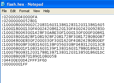
A hex is a hexadecimal source file used within many Programmable Logic Devices, being the most popular microcontrollers, to store configuration, data and memory directions that contribute to the execution of a program.
Explained more easily, a Hex File is what contains the program that we add to a microcontroller so it can operate the way we expect It. Things like changing the channels of our TVs to activating a security alarm at a certain time, all is programmed through a hex file.

Hex File Structure
Shoutout to Renesas
:0B0010006164647265737320676170A7
What is this nonsense?
This, my friend, is a line of Hex Code. If we open a hex file with our text editor, we'll see a lot of these chains of hexadecimal characters. But what does this mean?
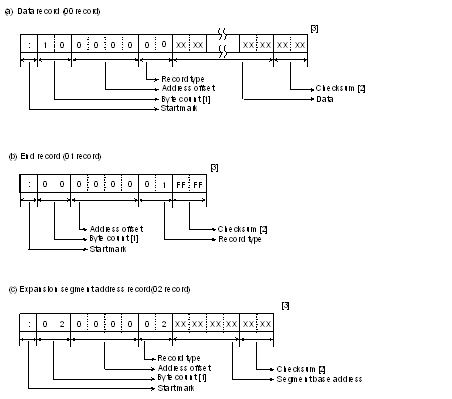
To get this, we have to understand the Hex File Structure. Analyzing this line:
- ":" Is what we use as our init code. We always use this at the beginning of a HEX line.
- The first hexadecimal pair (0B) is the Byte Count, which tells us how many bytes are in the data field of the line. If you don't know what this is, don't worry, We'll go over It in a sec.
- The next 4 digits (0010) is the starting 16-bit memory direction from where we'll init the data.
- The following byte (00), tells us the type of register, which explains the information contained in the data field.
- Then, the following bytes: 6164647265737320676170, concern the data field, where if we count Them as pairs, we can confirm that there are 11 (0B) bytes. The meaning of these bytes can vary according to the type of register.
- The final byte (A7) is the Checksum, a computed value that tells us If the line has errors or not.
Once we understand this, we have to take into account the different types of registers to see that each line can have a different function.

Register Type
Shoutout to Electronic Products
According to the microprocessor model, we can find that there are between 2 and 6 types of registers that we can use. According to their number, these are:
00: Data Register
The Data Field will contain instructions for the op code of our program.01: End Of File
Placed at the finishing line of the code, It tells us that the Hex File ends. Here the byte count is 00, the direction 0000 and we omit the data field.02: Extended Segment Address
This is used for instructions longer than 16 bits. In this case, the byte count will be 02 and the Data Field will contain a 16-bit segment base address.03: Start Segment Address
This is used for 80x86 (Intel 8086) microcontrollers, with a byte count of 04, where the data field first half will be the code segment and the last two hex pairs the instruction pointer.04: Extended Linear Address
This is for directions of 32 bits, where the byte count will always be 02 and the address will be omitted. In the data field, we put the upper 16 bits (2 bytes) of the 32 bits direction we want to access.05: Start Linear Address
Similar to the extended Linear Address, we use It to put a 32-bit address in the data field. However, here we'll put the full 4 bytes that comprehend the address in the data field. For this, the byte count will be 4 and we omit the address field.Since we'll read instructions from a PIC16F628A, an 8-bit microcontroller, we'll see most regularly the 00 and 01 instructions. Now, knowing this won't be enough to figure out how to read Hex files and what they mean.
That's why, we'll do the following:

Decyphering the code
Shoutout to Microcontrollers Lab
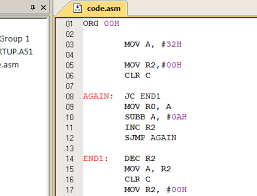
Now, If we take a look at the code of a simple assembler program where we'll mirror the state of the B Port with the A port:
__CONFIG 0X318

#INCLUDE <P16F628A.INC>
LIST P=16F628A

BSF STATUS,5
CLRF TRISA
MOVLW B'11111111'
MOVWF TRISB
BCF STATUS,5
MOVLW D'7'
MOVWF CMCON
CLRF PORTA
CLRF PORTB

PRINCIPAL
MOVF PORTB,0
MOVWF PORTA
GOTO PRINCIPAL
END
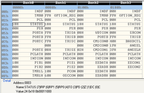
We can see that we're working with different memory directions, such as the Status Register to change memory banks and configure TrisA and TrisB to determine if PORTA and PORTB will be inputs/outputs. We also see that we're working with the "work" register and different bits. However, this is what we'll see in our IDE when the take a look at our .asm file.
If we check the .hex that's generated after compiling our program, we'll only see:
:020000040000FA
:1000000083168501FF308600831207309F0085012B
:0800100086010608850009289D
:02400E00180395
:00000001FF
Kinda different, right? Well, If we use what we've learned so far, we'll realize that the first line is an extended linear address type of register and the last one an "end of file" register. The rest of the lines just contain data. Here's where we'll see If It's exactly what has been written in the program.
First of all, we have to check our PIC's datasheet and look for the opcode section. But first, we have to understand what an opcode is:
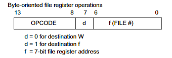
Whenever an instruction is recorded into our PICs, It's coded in a binary, 14-bit word, of which Its 6 most significant bits represent the opcode, which is the binary code for an operand like the instructions ADD, MOVWF, etc... Then, we just have to assign If we're using the work register or a selected register to store information. Finally, If the instruction involves recording a determined amount of bits, we write the decimal/hexadecimal/binary amount.
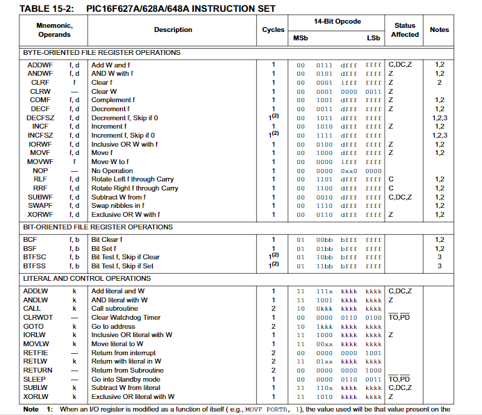
Once we know this, we search for the PIC16F628A Instruction Set. We notice that there's a 14-bit opcode column, which is what we'll take as a reference in our analysis:
But the opcode's still in binary and not in hex form. That's why we have to take our data field and convert It into a hex form. How do we do It? First of all, we take a look at the first data field from our Port mirroring program:
:1000000083168501FF308600831207309F0085012B
83168501FF308600831207309F008501, which we'll analyze every 2 bytes (4 hexadecimal digits). Then we chop It up:
But we still have to flip our bytes, putting the second hex pair first in each quadrant. If we do that, we'll get the following:
For example, If we convert 1683 from hexadecimal to binary, we'll get the number 0001011010000011, where If we take the 6 numbers after the first two initial zeros (Since the opcode is 14 bits long, not 16), we'll have 010110. Taking a look at our instruction set sheet, this is equal to the BSF instruction, where 101 will be pin 5 of the status register, represented as 0000011 in memory.
To verify the next operation, we just do the same. Converting 0185 to Binary:
0000000110000101
And take every number after the first two zeros: 00000110000101, we'll see That we're using CLRF on the TRISA register, which is represented as 10000101.
Then, we do the same with the other byte pairs, and we get:
- 30FF: MOVLW 11111111
- 0086: MOVWF TRISB(10000110)
- 1283: BCF STATUS in position 5.
- 3007: MOVLW 111 (Decimal 7)
- 009F: MOVWF CMCON
- 0185: CLRF PORTA (Since now we're in a different memory bank, In this position PORTA is located).
If we compare It with the Assembler code, we'll see that the code is the same. If you repeat It for the rest of the Data Lines, you will decipher the instructions applying the same method. Now that you understand hex code, you'll have a better understanding of how programmers work and how to handle specific memory positions within your programs.

The world of microcontroller programming is a vast, vast field, and this is what makes It so interesting. From figuring out how to create programs in different ways and implementing different sensors and accessories to understanding file structures, It's really hard to become bored here.

I hope this article could have been of use to you, providing you the tools you need to understand a hex file by just looking at It. Use this power wisely to create wonderful programs and broaden your knowledge about PICs.


Sources:
https://microcontrollerslab.com/pic-microcontroller-assembly-language/
http://www.elproducts.com/understanding-hex-files.html
https://tool-support.renesas.com/autoupdate/support/onlinehelp/csp/V4.01.00/CS+.chm/Compiler-CCRX.chm/Output/ccrx03c0402y.html